
|
|
Forum Index : Microcontroller and PC projects : Stepper Project
| Author | Message | ||||
| mozzie Guru Joined: 15/06/2020 Location: AustraliaPosts: 403 |
G'day Bryan, Sounds like we are having a similar week, every 5 min job ends up becoming a marathon... Doesn't help when the ToDo list is a couple of toilet rolls long and ever growing  As Phil says, the ON ERROR SKIP must be in the right place ' prog to test stepper functions Option default integer SetTick 200,Show_Pos ON ERROR SKIP ' this will skip one error only on the next line STEPPER CLOSE ' this will not cause an error due to the line above Stepper init Stepper axis x,gp0,gp1,,,200,400,50,5 Stepper axis y,gp2,gp3,,,400,600,100,5 Stepper position home Stepper run Stepper gc g1 x100 y80 f500 Stepper gc g0 x0 y0 etc etc... This can also be achieved with If peek(stepper active)>=0 Then Stepper Close You may be able to connect the output of the PicoMite to the DM556, the input is a optocoupler with a 270R resistor in series. Hook up 3v3 and measure current, anything more than 2mA should be ok.  $134 a litre.... Highway robbery, and they wonder why we resort to "alternative arrangements"  Happy to help mate, you have me thinking about automating the surface grinder here, another one day project Regards, Lyle. |
||||
| mozzie Guru Joined: 15/06/2020 Location: AustraliaPosts: 403 |
Bryan, Once you have the stepper system initialized, the axis's set up and homed (or positions set) and STEPPER RUN is active, the system sits in the background and waits until you send G-Code. Once the G-Code is in the buffer it will be executed in the background until the buffer empty's, it will then wait until more G-Code hits the buffer or STEPPER CLOSE / E-STOP happens. Like I said, it took me a while to get my head around this as you can be sitting at the prompt in terminal and the system is still working on G-code or waiting for more. Hope this helps. Regards, Lyle. |
||||
Bryan1 Guru Joined: 22/02/2006 Location: AustraliaPosts: 2155 |
Phill I am using that big board Peter designed and my daughter did leave me a LCD so could could bring the HDMIUSB board up to my shed as it does have a HDMI port with a keyboard, mouse and the PS4 which no joy has been with that  d dDistonow did say he shipped with it with V6.00 on so it does need flashing for the latest update. My other option is just bring up the 32" screen as it does have audio in that just works so I could use that instead of the LCD. I do need to order new dupont connectors but I do think that maybe an option so edits can be done in real time while I have the Bacoben top 500 going in the background which will make a change from JJJ. Now with that text file I made of the X Y Z axis for doing the perf plate which is over 700 lines if calling them one by one from a file on B: drive would that overload the buffer. So if we opened the cnc file off the SDCard we could read it line by line until the end of file but doing that is beyond the stepper code. As there are over 400 2mm holes in this file that drills copper getting this to work is a new task, now I have got coffee in the shed which has gone down well Getting that 32" screen up to my shed is my best option so no need for a 5 metre cable to the board. So now my task is setting up a 32" screen in my shed and making a mount for that TV screen so that HDMIUSB board can come up so what I can destroy it one day like my luck has been going it will go wrong Regards Bryan Edited 2026-04-18 19:17 by Bryan1 |
||||
| mozzie Guru Joined: 15/06/2020 Location: AustraliaPosts: 403 |
Bryan, The coil winder machine has a separate G-Code file for each coil type, these are read in by the main program and sent to the G-Code buffer one line at a time. You can use Peek(Stepper Buffer) to see how much room is in the buffer and wait until room becomes available, should allow unlimited G-Code files Hopefully you get the HDMI unit working, being able to edit files and see error messages in real time will make life much easier. Another problem: the STEP pulses from the PicoMite are around 1.5uS long and the DM556 expects a pulse of 2.5uS minimum, so even if 3.3V is enough to drive the input the pulse width may still be too short. You may need a pulse stretcher as well. Regards, Lyle. |
||||
| Bryan1 Guru Joined: 22/02/2006 Location: AustraliaPosts: 2155 |
So finally got around to bringing up my HDMIUSB board and TV to the shed and set it up, now as it had V6.00 on flashed it with the latest B5 beta so I could try the new FM file manager. Well just typing fm worked so the first job was too see if I could get a MP3 playing, well the screen did say it was playing so put the volume upto 100% yet still no sound. Also kept getting a message the RTC wasn't responding. Next tried to connect via the com port only to find although the computer beeped in device manager only com3 was there so couldn't connect at all. So reflashed with V6.02 and got com11 to connect to, now I did manage to get tera term installed and all showed was gobbly gook so as V6.02 doesn't have the FM I tried via MMEdit to install and just got this Connected to COM11 at 19200 ☼C:\Users\Bryan\Downloads\2025-07-27_193559_FM175\FM175.bas Uploading using: 'target port\COM11:19200 s\picomite Upload started Not responding! Now see that icon before C: it came up when it connected so don't know what that is. One other thing in V6.02B5 with the RTC not responding the I2C was set after I did the OPTION platform HDMIUSB where in V6.02 I went to set the time only to find the I2C went an error saying it wasn't set. Edited 2026-04-20 16:36 by Bryan1 |
||||
| Bryan1 Guru Joined: 22/02/2006 Location: AustraliaPosts: 2155 |
Now I did set the Audio to GP10, GP11', on Channel 5 as I found that setting on a forum post from a few months ago but what is the correct Audio setting. Silly me didn't look at the V6.0 setup so in the woods here |
||||
| matherp Guru Joined: 11/12/2012 Location: United KingdomPosts: 11636 |
It should say how to configure the board on the silkscreen. Depending on which version it will be either: OPTION RESET HDMIUSB or OPTION RESET HDMIUSBI2S These commands do everything needed. Note V6.02.02B8 just posted has increased the stepper pulse - try it - untested |
||||
| Bryan1 Guru Joined: 22/02/2006 Location: AustraliaPosts: 2155 |
Thanks for that Peter I did try option reset HDMIUSB and it didn't setup all the options so after my caffine intake I will do the option HDMIUSBI2S. With my big board I have got the B5 beta so I will try that new one and see how it goes and report back. |
||||
| Bryan1 Guru Joined: 22/02/2006 Location: AustraliaPosts: 2155 |
Well it was my bad and has Mozzie did post a 5 minute job can open a can of worms  Silly me as I just put B8 on my HDMIUSB computer trying a option reset HDMIUSBI2S got a message saying that option IS ONLY for 2350B boards So did the option reset HDMUUSB and YES all the options came up Anyway found the problem with the audio as I had to reset the LCD TV with the audio by setting the input to analogue next thing after a click had the Doors belting out a classic So getting the audio to stop is my next quest to learn.Now once again a grey moment and here I thought I had bricked the big board as there was no way win10 would see a connection silly me flashed the HDMIUSB B8 in instead of the 2350B8.uf file. Now as soon as flashed that in MCCC came up with new ports added and COM11 was assigned Do think it's time for a shed caffine then it's case of going back in this thread so I can load all the options for the lcd and move on...Regards Bryan Edited 2026-04-21 10:07 by Bryan1 |
||||
| phil99 Guru Joined: 11/02/2018 Location: AustraliaPosts: 3321 |
Clear_Flash_2350 |
||||
| Bryan1 Guru Joined: 22/02/2006 Location: AustraliaPosts: 2155 |
Ok got the big board all setup and no movement on the DM556 yet now I know I probably did the wrong thing but just had to try it pulled up the DM556 to the 5 volt pin on the board. This is the step pin Channel 1 is connected to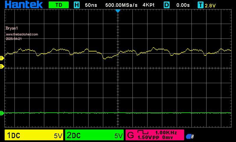 So I think is time to make that 5 volt board using a BC547 and the resistors then having another go |
||||
| phil99 Guru Joined: 11/02/2018 Location: AustraliaPosts: 3321 |
Lyle mentioned that some inputs need inverting. https://www.thebackshed.com/forum/ViewTopic.php?TID=18787&P=7#253744 See the post with footnote here for the transistor connections, including inverted. |
||||
| Bryan1 Guru Joined: 22/02/2006 Location: AustraliaPosts: 2155 |
Ok made up the 5 volt board using BC337 trannys as I have plenty of them here and getting closer 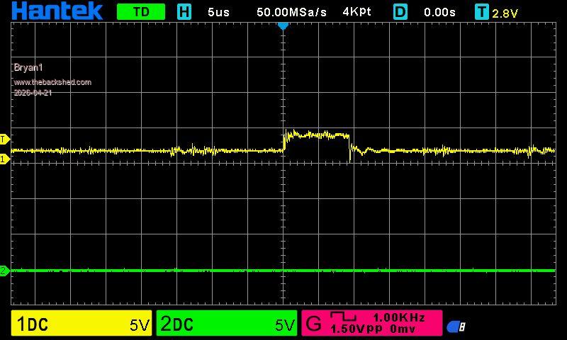 Phill I didn't use enable as it is an option and the DM556 can work without using it Edit: just ran the code with Channel 1 just connected to GP26 which is the step pin and it was a tad cleaner trace but the same as the picture above 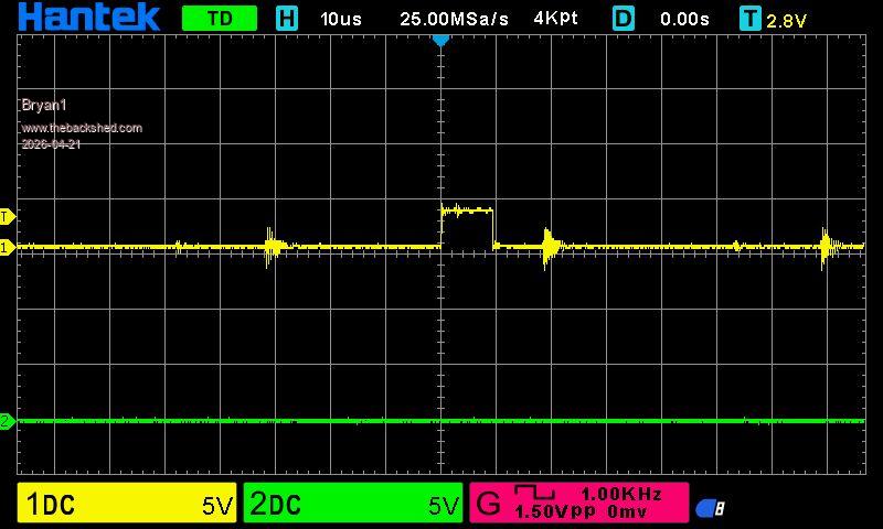 Edited 2026-04-21 11:44 by Bryan1 |
||||
| Bryan1 Guru Joined: 22/02/2006 Location: AustraliaPosts: 2155 |
YAY got finally got the DM556 working thought I would try putting the wires to ground as in the grey moments had them pulled up and saw the dial indicator move So now off to Ebay to buy 3 new DM556's for the surface grinder and man we have lift off........ Edit: just noticed I had the 5 volt pull up in the hole beside the 4.7K resistor and while doing a run the scope did confirm it is running on 3V3 Here is a scope pic of it running  Edited 2026-04-21 13:19 by Bryan1 |
||||
| Bryan1 Guru Joined: 22/02/2006 Location: AustraliaPosts: 2155 |
Cool found the DM556's for $18 each with an ETA of the 24th to the 29th of this month so time to get making a coupling for the Y axis as that will be the first one done for testing. Now Peter a huge thank you for modifying the Stepper Code and I'm sure Mozzie and myself will be having heaps of fun automating our surface grinders so it can run off the stepper code.Regards Bryan Edited 2026-04-21 13:04 by Bryan1 |
||||
| Bryan1 Guru Joined: 22/02/2006 Location: AustraliaPosts: 2155 |
Now having a bit of play with this and one thing I found where I have set in Mach3 282 step/min which is accurate to a thou going 1100 steps with the code only goes 0.95mm, now as there is a nice spike when it goes high I set the scope to 2 volts to capture it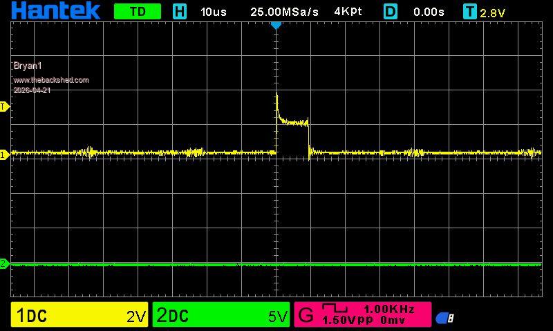 Now I have used the 5 volts on the cnc board for the pullup on the collectors and the probe for Channel 1 is on the collector for the step pin yet it clearly shows a lower voltage for the step trace. On reading the Stepper PDF I enable the Scurve thinking it smooth that spike and no matter what I set the Stepper Jerk value I get the error it is too low even when I set to the step/mil figure so a bit to learn with this command. |
||||
| phil99 Guru Joined: 11/02/2018 Location: AustraliaPosts: 3321 |
See the circuit diagram in Lyle's post at the top of this page. It shows the 3 input (+) terminals connected to Vcc. Make sure they are connected to 5V, not 3.3V. Edit. Downloaded the DM556 manual. Here are the relevant bits. Logic signal current 7min 10typ 16max mA PIN Details PUL+, PUL- Pulse Connection: Required. (1) 5V / 24V, optically isolated, differential. (2) Maximum 200 KHz input frequency. (3) Pulse width of 2.5μs or longer. (4) In single pulse (step & direction) control mode, this input signal represents a pulse which is active at the rising or falling voltage edge (set by DIP switch SW13); in double pulse (CW/CCW) control mode, this input signal represents clockwise (CW) pulse which is active at both high voltage level and low voltage level. So it looks like the transistors should be wired to invert the signals. 10kΩ from Pico pin to base, emitter to ground and collector to input (-). All input (+) to 5V. Pullup resistors not needed. With the scope connected between input(-) and Gnd. you should see inverted pulses going from about 4.5V to 0V Edited 2026-04-21 14:58 by phil99 |
||||
| Bryan1 Guru Joined: 22/02/2006 Location: AustraliaPosts: 2155 |
Ok just did the change Phil and looks like for once I got it right 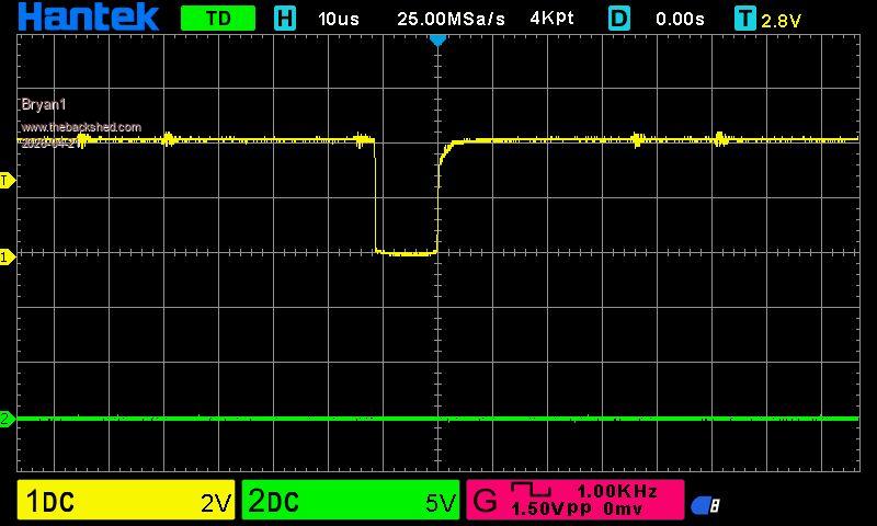 Regards Bryan |
||||
| phil99 Guru Joined: 11/02/2018 Location: AustraliaPosts: 3321 |
As for the number of steps per mm see page 9 of the manual. It looks like the stepping mode can be configured with the DIP switches. Edited 2026-04-21 15:42 by phil99 |
||||
| Bryan1 Guru Joined: 22/02/2006 Location: AustraliaPosts: 2155 |
So just tried to print the buffer and keep getting a syntax error  OPTION EXPLICIT Option default integer on error skip Stepper close SetTick 200,Show_Pos Stepper init 0.05, 150, GP22 STEPPER HWLimits GP23, GP21, GP20, GP19, GP18, GP17 Stepper Axis X, GP26, GP25,1,0,1100,100,100 Stepper limits X, -100, 200 Stepper Scurve 1 'Stepper Jerk 955 Stepper position home Stepper run Stepper gc g1 x-5 f100 Stepper gc g1 x 0 Stepper gc g1 x-5 Stepper gc g1 x 0 Do Pause 100 Loop Until Peek(stepper active)=0 ' wait until motion complete Pause 250 ' wait for final position update Stepper close End Sub Show_Pos Print @(100,100),"X-POS= " Str$(Peek(stepper x),-4,4) 'Print @(100,120),"X Buffer " Str$(Peek(buffer x),-4,4) End Sub I have commented it out as it keeps going the error. |
||||
| The Back Shed's forum code is written, and hosted, in Australia. | © JAQ Software 2026 |
