
|
|
Forum Index : Electronics : Bryan's Inverter build
| Author | Message | ||||
Bryan1 Guru Joined: 22/02/2006 Location: AustraliaPosts: 2155 |
So if I'm right the problem may be with the VFB so may be back to looking and checking components on the control board VFB section. It maybe a simple solder joint where the board is double sided and with me soldering the back the solder didn't flow thru to connect the top pad. Now when I first started the inverter the voltage was around 130 volts off memory and I used the pot on the VFB part of the control board to get a 230AC output. Well they do say building you're first inverter will get you knowing everything about it but in my case it does seem I am finding EVERY problem there is  |
||||
| Bryan1 Guru Joined: 22/02/2006 Location: AustraliaPosts: 2155 |
Now with my first test TinyT did point out 22.1 x 200.1 = 4420VA or watts Now ohms law doesn't lie and if these energy meters are accurate why didn't it show the true value, I did notice when I had the dual element going then I went and turned on the toaster oven and saw 3Kw on the meter adding the 1.5Kw single element only showed about 400 watts more. It has been years since since my shed has seen these power levels in fact time for a /Blog In late 2004 I emailed a company in Tiawon with the same specifications as my Selectronic SA32 inverter that has been going on my house since 2005 as I working at Telfer Gold Mine on a 28x7 roster. Anyway got a email back from Tiawon saying in order to not get you import charge I will make you one for $999 so you don't pay import duty. Well when the package arrived in Australia I had to use an import agent and customs asked me what the package was where I said it was an inverter where 24 volts DC in put in and 240 volts AC is put out so it will power a house. They asked me 4 times what it was then come to the conclusion inverters wasn't on the import list so I got charged for import duty. In all I got the Kipoint inverter home for just under 2K  and a score of used telsux batteries saw me power my off grid shed for the first time off solar. and a score of used telsux batteries saw me power my off grid shed for the first time off solar.Now in 2012 I got onto used forklift batteries where I sold enough of them to take 12 months off work Honestly the rest is history as house is setup for it's 600AH 24 volt battery and my shed has a 735AH and both are still working today. I did learn the lesson of not grinding near the battery and blew the top of a cell on my shed battery So that blue cloth you see in my pic's is that cell and it does give the idea when it's low time to water the battery. On my house array every month since I put that 1.9Kw array on I check the water levels on the 600AH battery. Around 5-6 litres now like summer as the batteries were in float mode by lunch time the check was every week Lets get back to my Kipoint inverter I scored the old stove from Wistow's post office, found it was put in 1850 and can you believe it's still a work in progress Anyway I had a job to do and the Kipoint did power my arc welder, I made sure the SG was on 1024 or better then spent 5 hours arc welding up the 2 ovens that were needed. The next day my 8" grinder wouldn't start so I did think I did kill the surge on the inverter. Around 2 weeks later the 8" grinder did start so I thought all was good and although this inverter did go a fault I took it to Roger and mentioned the green power pot and sure enough that was the problem where it went 2Kw easily. Now many of you will ask why I'm still on 24 volts well the system I put in just works so why change it where 48 volt systems were a dream. All these years later I want to change it so I can have real power so this inverter project has taken over 2 years to make and every problem there is building I seem to find the all the problems one can find building my own. The support I have gotten is golden from from members to help me in this task of getting my first build going. My main plan as I do have 6.3Kw of 330 watt panels I put 3 of them beside my shed which is the main reason why the SG is pointing to not quite 100% but good enough. Now I do plan when this inverter is going to add those panels to my roof so I can put one of those 5Kw grid tie inverters in so my shed is upto date with modern times so I can get my machineshop back so I can back on line. The 2 lathes and my bridgeport mill still work of the Kipoint as I put VFD's on each so I could run 3 phase off 240 volts. But it time to fix what is working with new stuff so guy's guess my trade /end blog |
||||
| phil99 Guru Joined: 11/02/2018 Location: AustraliaPosts: 3321 |
Perhaps take 1 turn off the primary, assuming the battery volts aren't sagging too much (measured at the MOSFETS). |
||||
| Bryan1 Guru Joined: 22/02/2006 Location: AustraliaPosts: 2155 |
Ok explain how one turn off the primary can solve this problem? |
||||
| phil99 Guru Joined: 11/02/2018 Location: AustraliaPosts: 3321 |
Removing 1 primary turn will increase the turns ratio, increasing the maximum possible output voltage when the PWM drive reaches 99%. It may however increase the idle current, depending on how much headroom there is between the magnetizing current and saturation. The other option is to add extra turns to the secondary, 20 to 30 perhaps. This won't affect idle current but will increase resistance loss at high power a bit. There is no free lunch! |
||||
| tinyt Guru Joined: 12/11/2017 Location: United StatesPosts: 561 |
I suggest to 'scope the AC output waveform using an isolation transformer. If pwm is close to 100% I am guessing that the waveform peaks will be clipped. Assuming VB = 22 volts is an accurate voltage at the inverter input, find out if there is excessive wiring voltage drop from the battery terminals to the inverter input with a 3 kW AC load: Battery terminal voltage = ? Inverter power input terminal voltage = ? |
||||
| KeepIS Guru Joined: 13/10/2014 Location: AustraliaPosts: 2199 |
No, the waveform peaks will not be clipped, poida has always made sure that his SPWM code will never go above 99% PWM for obvious reasons. NANO:Inverter V 8.2ks - Linux AvrDude GUI script V4.1 |
||||
| Bryan1 Guru Joined: 22/02/2006 Location: AustraliaPosts: 2155 |
Ok new day and I have set the VFB to 240 volts, So with a 1.7K load the AC voltage 244 volts with Vbat showing 23.3 and the LCD showing 23. Now I took one turn out from the primary and with a 3.2 Kw load AC voltage 213 volts Vbat showing 22.6 and the LCD 22 volts So raising the VFB to 240 volts AC has helped a bit and removing one turn also helped I think. So basically one say I need more turns on the secondary which means I need to make a setup and get one of those hoops so I can wind more turns on the secondary. If you guy's want to suggest more tests I can do them. Edited 2026-04-12 10:57 by Bryan1 |
||||
| Bryan1 Guru Joined: 22/02/2006 Location: AustraliaPosts: 2155 |
Well decide to test my mig welder out and did a 75mm fillet weld @110 amps and 18 volts and it just worked Now I need to talk nice with my missus so she can come up to the shed and take a pic of the energy meter . |
||||
| Bryan1 Guru Joined: 22/02/2006 Location: AustraliaPosts: 2155 |
Ok seems I did talk nice enough 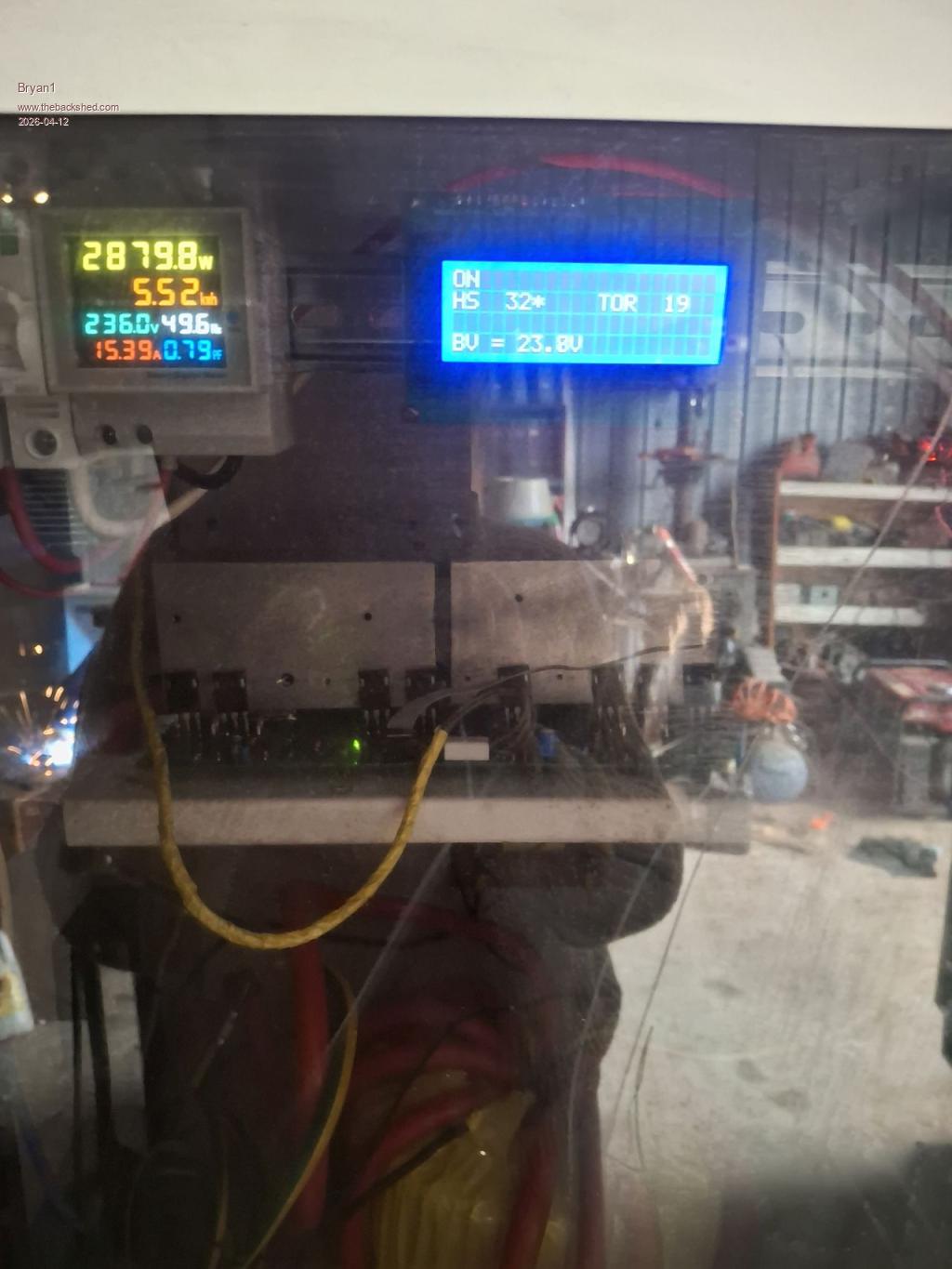 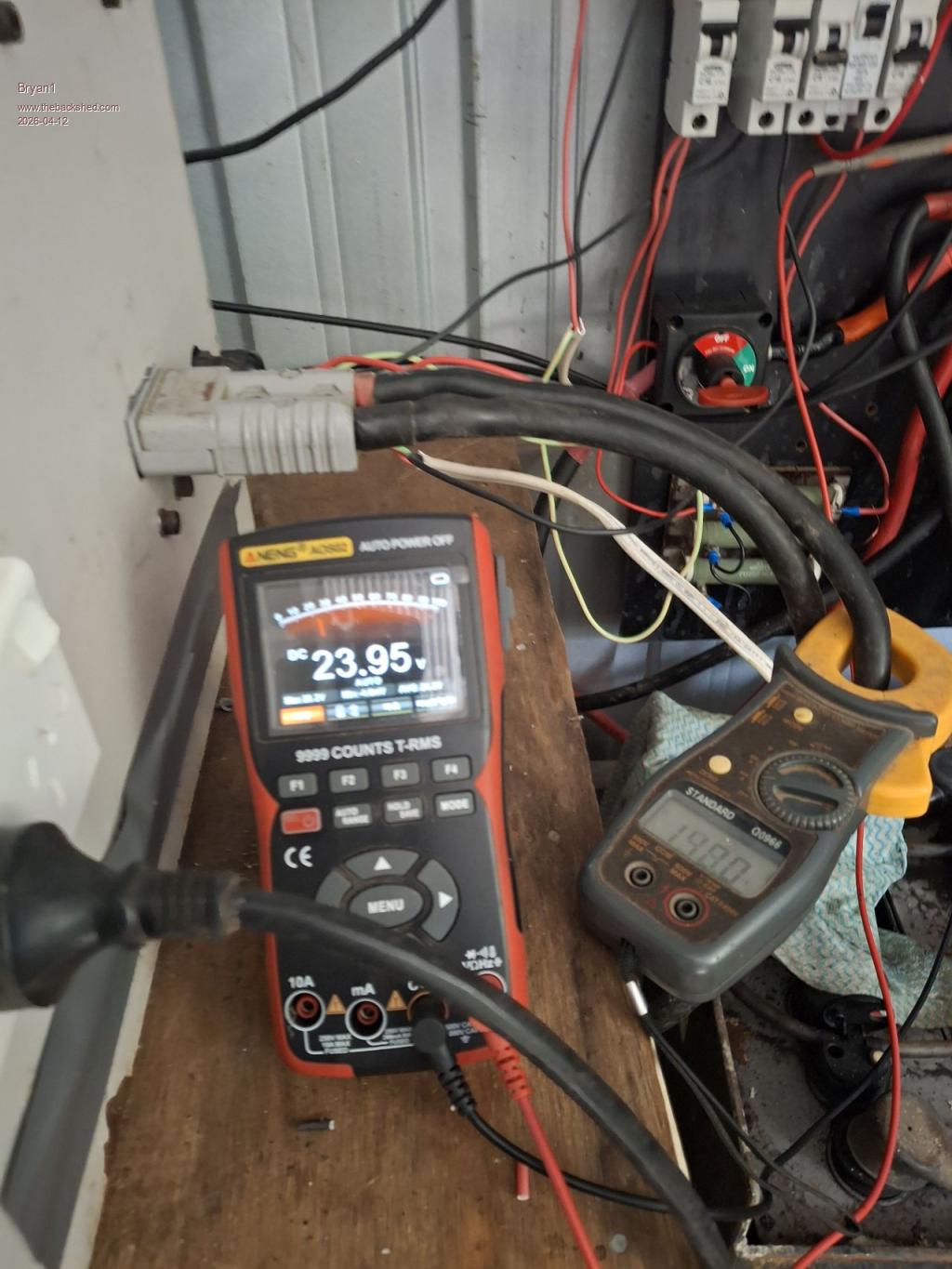 Now of course the fillet weld 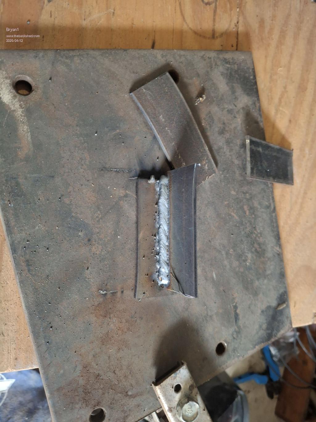 Now Vbat 23.95 volts and with a 148 DC current draw 148 x 23.95 = 3544.6 The energy meter 2879.8 So 664.8 watts difference. Also the AC volt voltage dropped to 236 AC volts which is 5 volts under the VFB so much better regulation than with a non resistive load I do think Regards Bryan Edited 2026-04-12 11:33 by Bryan1 |
||||
| phil99 Guru Joined: 11/02/2018 Location: AustraliaPosts: 3321 |
236V at almost 3kW with a reactive load looks good enough to me. Unless others who have built this design say otherwise perhaps leave the secondary as it is. |
||||
| KeepIS Guru Joined: 13/10/2014 Location: AustraliaPosts: 2199 |
Earlier in your toroid build, it indicated that the mag current was around 10.9 watts with 240vac across the secondary winding, after you had added the extra turns. That indicates that the secondary winding is in the ballpark for the correct number of turns for that toroid. Only the primary winding needed to be adjusted to get VFB to start working correctly. The correct place to measure the DC voltage, "UNDER LOAD", is across the DC terminals right at the Power Board terminals or solder connections (carefully!!!). I agree with phil99, looks fine for now, keep an eye on the AC regulation under a few high loads, just to be sure you know what the limits are with the current setup. NANO:Inverter V 8.2ks - Linux AvrDude GUI script V4.1 |
||||
| Bryan1 Guru Joined: 22/02/2006 Location: AustraliaPosts: 2155 |
Just dialed in the setup to get a much better weld and welded around 200mm of scrap and no complaints from the inverter So finally got my mig welder going Well as the mig is drawing around 3Kw that would be the biggest load and to see it just work has me one happy camper Now for powering large resistive loads I will have to setup a 3Kw string of my 330 watt solar panels and install one of my 5Kw Grid Tie inverters to power the load and take the strain off the inverter. Edited 2026-04-12 11:59 by Bryan1 |
||||
| tinyt Guru Joined: 12/11/2017 Location: United StatesPosts: 561 |
81.2% Efficiency |
||||
| Bryan1 Guru Joined: 22/02/2006 Location: AustraliaPosts: 2155 |
Just googled 81.2% efficiency and the AI did say it was down and 90% or better is the best. So with 18.8% going in heat just looked at my battery cables and from the battery terminals to my DC board the cable length is about 2 metres. So this week I will get some shorter cables and see that can can improve the efficiency as shorter cable should produce less heat. The 12 volt shop has plenty of thick cable so I'll go see them and get the new cables made as an Anderson connector does need to go on so the battery can be isolated. |
||||
| phil99 Guru Joined: 11/02/2018 Location: AustraliaPosts: 3321 |
I have my doubts about the DC clamp meter reading. The high frequency ripple on the DC may be giving a false high reading. The lost Watts don't just disappear, they get converted to heat. Check the temperature of everything between the battery and the inverter with a load of 2kW or more. 80% efficiency would mean 500W is being turned to heat (2.5kW in x 80% = 2kW out). That would make the cables, connectors, toroid or heatsinks too hot to touch, perhaps hot enough to melt the cable insulation. If they are just warm then you are not loosing that much. |
||||
| Bryan1 Guru Joined: 22/02/2006 Location: AustraliaPosts: 2155 |
Ok this time I put the clamp meter close to the negative battery terminal, turned on the toaster oven and one element. 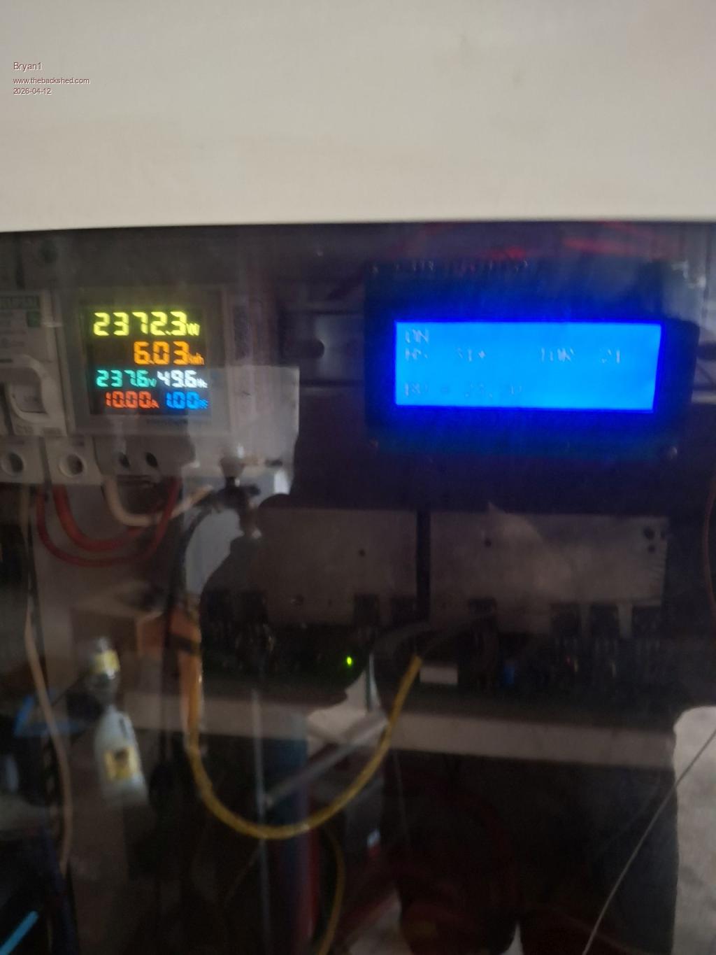 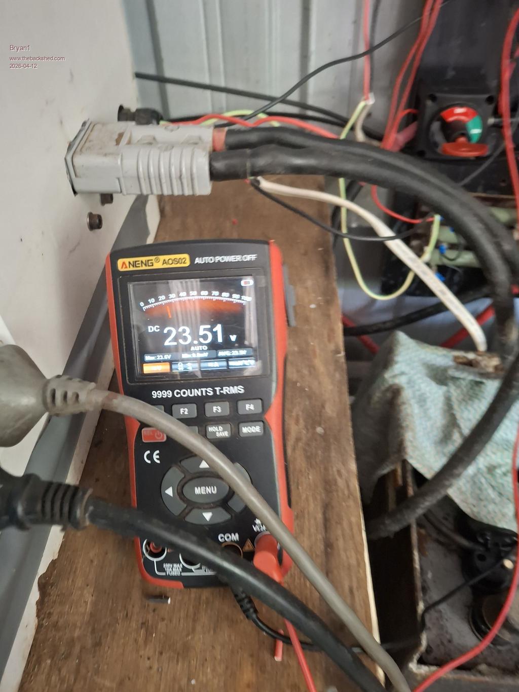 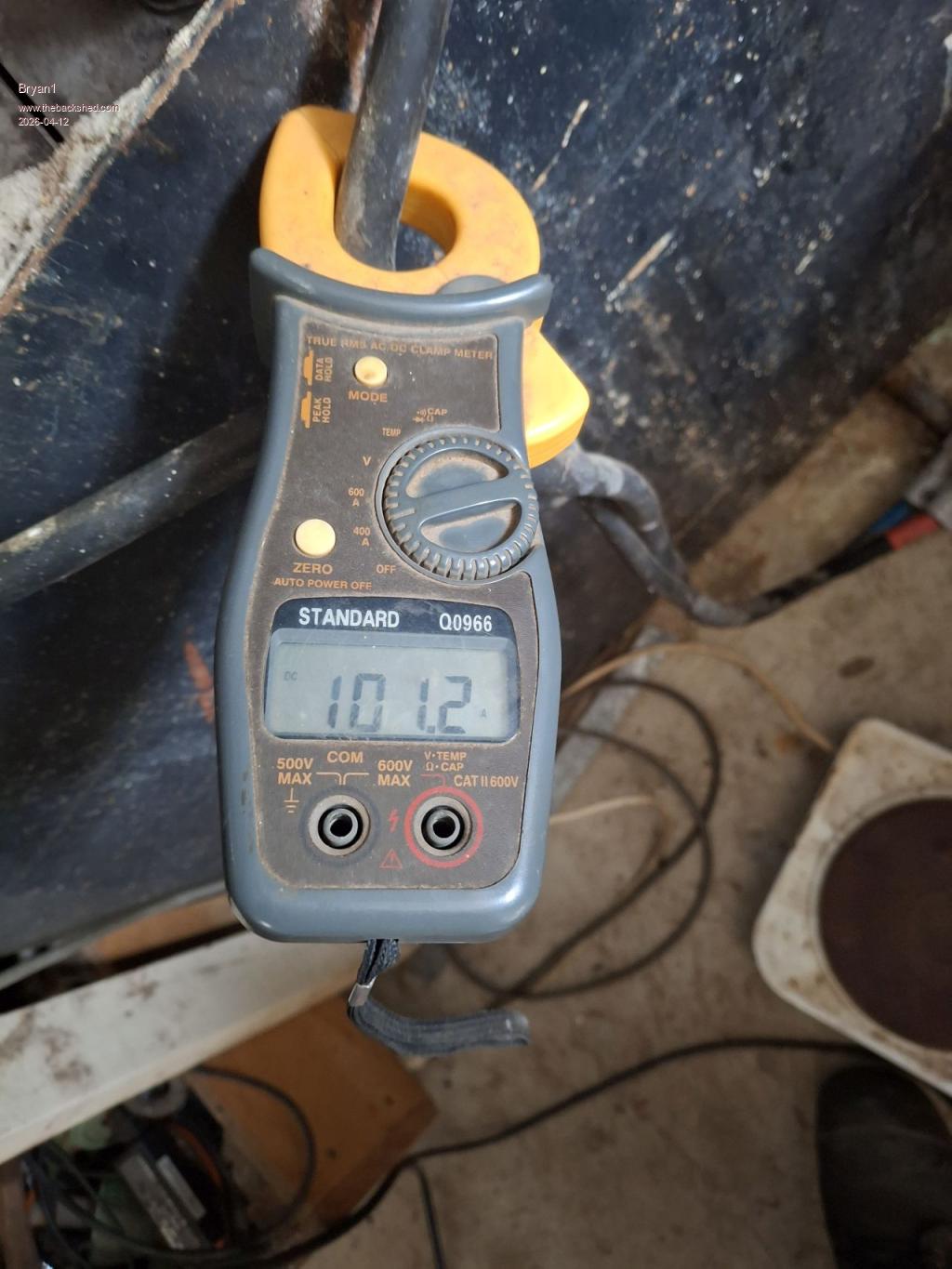 Now 23.51 x 101.2 = 2379.2 The energy meter 2372.3 so that a lot better, now the AC voltage was 235 volts and I did notice turning on a 2nd element caused the voltage to drop to 215 volts. Also while I was doing this test I did feel all the cables and no heat was felt. Now with the primary it was 14 turns and with one turn taken off the regulation was much better, now with these resistive loads going above 3Kw does cause the voltage to drop off so maybe taking one more turn out so 12 turns may be a better match. This would mean I will need to rewind the primary so the output cables are close to equal then I could bury the temp sensor better to get a true TOR reading as I did notice the toroid was warm to the touch this morning. Edited 2026-04-12 14:37 by Bryan1 |
||||
| phil99 Guru Joined: 11/02/2018 Location: AustraliaPosts: 3321 |
Removing another turn could possibly increase idle current, making it run even warmer. Maybe wait to see what others think. Taking off more may also reduce the overload safety margin, which is needed for motor starting etc. |
||||
| Bryan1 Guru Joined: 22/02/2006 Location: AustraliaPosts: 2155 |
Well that was interesting just fired up my 8" grinder which has sat idle ever since I killed the surge on my Kipoint where the inverter used to run it fine. Used an extension cord and had the on switch on the grinder, now when I turned it on saw a quick glimpse of 8Kw on the energy meter on startup then it dropped down to 2Kw. Once it was upto speed the current draw with the shed around 400 watts. So thats the first time I seen the surge work so glad I got my 8" grinder back Now I'm not game as I do have a 25 year old 3Kw air conditioner, I used to run it on my 16hp listeroid engine where I found when hitting the cool switch it used to toss the belt off the engine as the current draw acted like a brake on on the 5Kw genhead. Edited 2026-04-12 15:43 by Bryan1 |
||||
| Bryan1 Guru Joined: 22/02/2006 Location: AustraliaPosts: 2155 |
Ok decided to take a video of the 8" grinder starting up and the energy meter response. Now the huge surge I saw before was the first time I started this grinder and the cobwebs are all gone so the surge is a tad tamer It could be a minute of your life you don't get back Edited 2026-04-12 16:10 by Bryan1 |
||||
| The Back Shed's forum code is written, and hosted, in Australia. | © JAQ Software 2026 |
