Notice. New forum software under development. It's going to miss a few functions and look a bit ugly for a while, but I'm working on it full time now as the old forum was too unstable. Couple days, all good. If you notice any issues, please contact me.
Bryan1 Guru Joined: 22/02/2006 Location: AustraliaPosts: 2155
Posted: 06:12am 02 Apr 2026
Copy link to clipboard
Print this post
Now thinking back to my last test after I put all those scope pic's up with no replies I did think everything was right
I had the power supply set to 26 volts 400mA current and the voltage did rise to around 160volts AC then a click click click coming from the power board. The AC voltage dropped to zero and the power supply was drawing the full 400mA.
So the question after the AC voltage was ramping up why did it fail and go that clicking sound as the board has passive parts.
phil99 Guru Joined: 11/02/2018 Location: AustraliaPosts: 3321
Posted: 07:24am 02 Apr 2026
Copy link to clipboard
Print this post
My guess is it is that bank of big caps suddenly discharging when something reaches it's breakdown voltage. The caps recharge at the current limit until the cycle repeats.
To see if this is the case reduce the current limit to slow the recharge down and monitor the voltage across the caps. It should slowly rise then suddenly fall.
They can discharge thousands of amps into a short which means your power supply current limit gives no protection at all. Remove them until all faults have been found.
E = 0.5 * C * V^2 where E = energy (Watt Seconds), C = Farads, V = Volts
E = 0.5 * 0.06 * 26^2 = 20.28 Watt Seconds
So if the discharge lasts 1mS that is a 20kW pulse! More than enough to destroy MOSFETs etc.
(If the discharge lasts 0.1mS that is a 200kW pulse!) Edited 2026-04-02 17:28 by phil99
Revlac Guru Joined: 31/12/2016 Location: AustraliaPosts: 1285
Posted: 07:36am 02 Apr 2026
Copy link to clipboard
Print this post
I thought it looked ok too, but I never measured (this test inverter on the bench) that way, now at 23vdc and 400mA I get 144vac on this one, not sure why yours was clicking unless its the power supply limit and the invert wants more to reach 230vac? See the photo of it working 2 pages back. Edit: last photo is the working one.
Was it the power supply clicking and the inverter is still ok or is something shorted again? Edited 2026-04-02 17:41 by RevlacCheers Aaron Off The Grid
Godoh Guru Joined: 26/09/2020 Location: AustraliaPosts: 678
Posted: 07:57am 02 Apr 2026
Copy link to clipboard
Print this post
I remember when Oztules was about that he always suggested removing the capacitors when testing a repaired board. That is the process I used when fixing my Powerjacks when they blew up. Took the caps off the board replaced mosfets and sometimes drivers test board, if it works then put capacitors back on and cross fingers
mab1 Senior Member Joined: 10/02/2015 Location: United KingdomPosts: 282
Posted: 08:21am 02 Apr 2026
Copy link to clipboard
Print this post
Well the scope waveforms seem ok.
I assume this was on the bench psu? What did you have the current limit set to?
Just thinking that the clicking/flickering display could be the result of hitting the current limit of the psu rather than a fault - if the current draw > the psu limit the voltage would drop, possibly causing the driver board to stop and restart. but it would be helpful to know what the current limit was set to at the time.
tinyt Guru Joined: 12/11/2017 Location: United StatesPosts: 561
Posted: 12:30pm 02 Apr 2026
Copy link to clipboard
Print this post
Those scope pics look OK. I was too busy with other things and was not able to reply. Apologies.
It would also help to post exactly where the scope probes are connected. Edited 2026-04-02 22:33 by tinyt
Bryan1 Guru Joined: 22/02/2006 Location: AustraliaPosts: 2155
Posted: 10:43pm 03 Apr 2026
Copy link to clipboard
Print this post
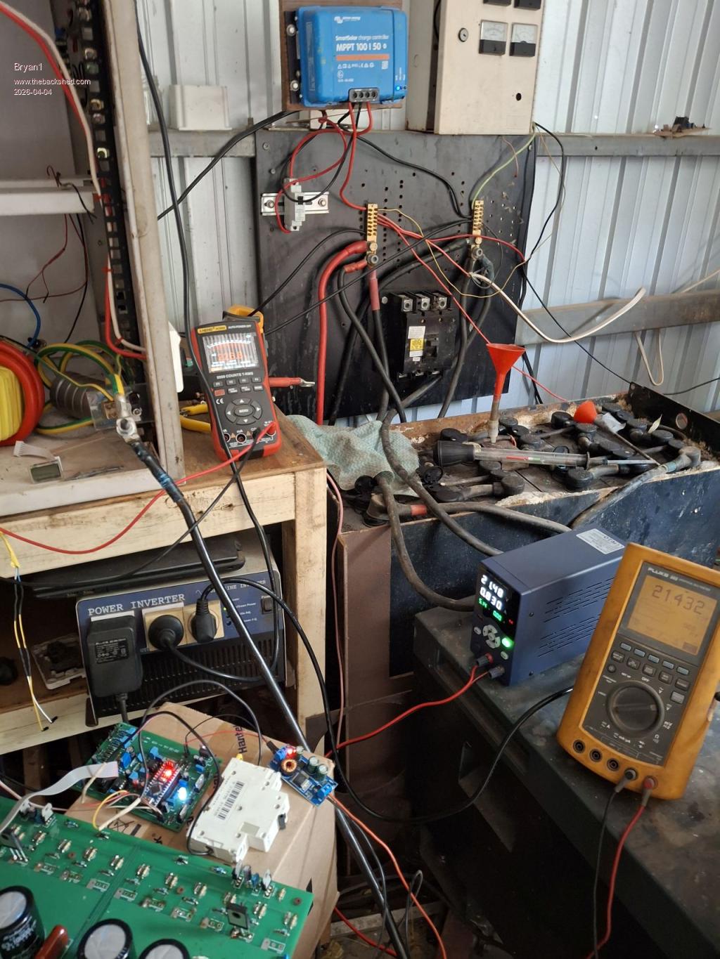
Ok with a fresh start decided to set the board backup and this time I set the power supply to 800mA
They do say a picture is a thousand words
So looks like it was the power supply was set too low Edited 2026-04-04 08:55 by Bryan1
Bryan1 Guru Joined: 22/02/2006 Location: AustraliaPosts: 2155
Posted: 11:16pm 03 Apr 2026
Copy link to clipboard
Print this post
Now that first test was with the AC output disconnected from the AC board so I could see if the AC voltage was right.
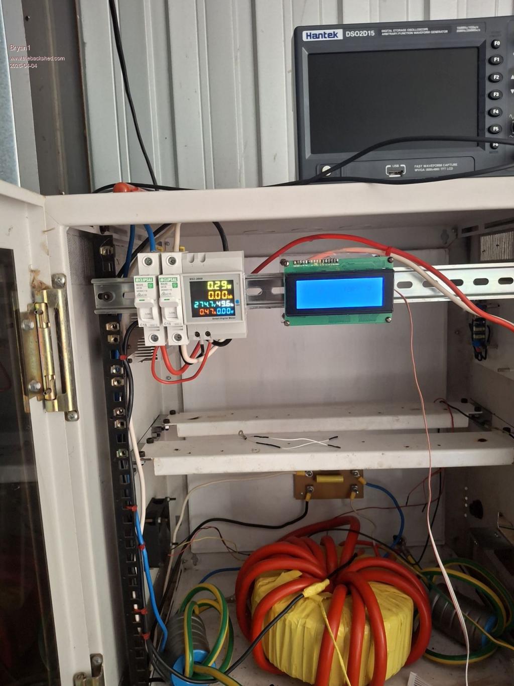
Connected the toroid AC outputs back onto the AC board and finally the energy meter came to life
One happy camper and a huge Thank You for all the members that have helped me with this inverter project.
Now with that Ali inverter board it can become one piece of the puzzle for wiring up my shearing shed.
Edit: as the voltage was 274AC I shut it down and let the caps discharge, set the power supply to 4 amps and hooked up the VFB wires and turned it back on. Saw the AC voltage was 120 volts so used the trim pot to adjust the voltage to 230V AC
One thing I do need to do is set that Vbat option in the code as it's 0.5 volts over the Vbat and trying to get that magic number is proving to be some fun. Edited 2026-04-04 09:47 by Bryan1
Bryan1 Guru Joined: 22/02/2006 Location: AustraliaPosts: 2155
Posted: 12:44am 04 Apr 2026
Copy link to clipboard
Print this post
Ok found that magic number 0.05860 got the BV on the lcd showing 26.0 volts
Now the energy meter is showing 231 volts AC and 0.39 amps and the power supply is set on 26 volts with a 0.760 the average current reading.
So may be time to put the rest of the mosfets on the board and install the inverter in the box but in no hurry as this has taken so long to get right.
Bryan1 Guru Joined: 22/02/2006 Location: AustraliaPosts: 2155
Posted: 02:18am 04 Apr 2026
Copy link to clipboard
Print this post
Ok so I do think we need to see the AC waveform which is a totally new thing for me using a scope.
It has been said one would need a wall wort or a small transformer when we already have one on the AC board being the 12Vac for the VFB.
So hooking a probe the diode on the brainboard where VFB comes in but where would the ground go?
I have tried googling this and not finding the right answer I need.
tinyt Guru Joined: 12/11/2017 Location: United StatesPosts: 561
Posted: 02:46am 04 Apr 2026
Copy link to clipboard
Print this post
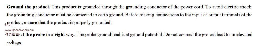
Your 'scope manual says:
So, to play safe, I would use another 230vac:12vac isolation transformer and connect its 230vac to the inverter 230vac output. Then the scope probe tip and probe gnd to the 12vac output of this transformer.
Edit; If you have a battery operated 'scope to use, then there is no need for this second isolation transformer. Edited 2026-04-04 12:49 by tinyt
Bryan1 Guru Joined: 22/02/2006 Location: AustraliaPosts: 2155
Posted: 03:25am 04 Apr 2026
Copy link to clipboard
Print this post
Thanks that TinyT I found an old transformer so hooked up a power cord and did the first test with my DMM, 29 VAC with the 240 volt coming from my Kipoint inverter.
So hooked up to the inverter
Regards Bryan
This is the transformer I used
Edited 2026-04-04 13:32 by Bryan1
Godoh Guru Joined: 26/09/2020 Location: AustraliaPosts: 678
Posted: 07:57pm 04 Apr 2026
Copy link to clipboard
Print this post
Fantastic Bryan, so good to see that the inverter is working and that you have got it working. There are a lot of things that throw us off the track, so good to see you are nearly there. Good luck with fitting the rest of the parts and putting it all together. It will be great to see how it goes and how it works on real loads Pete
Bryan1 Guru Joined: 22/02/2006 Location: AustraliaPosts: 2155
Posted: 06:45am 07 Apr 2026
Copy link to clipboard
Print this post
Well finally had a couple of hours this afternoon so soldered in 4 mosfets to each leg and as it's getting late in the day tomorrow morning I will fit if time allows the power board back in to the cabinet. Also got the control board back in with everything hooked up and ready to go.
Now I'm going to take the Kipoint Inverter off line so I have the space on the positive bussbar on my DC power board to place the isolation switch. So the inverter side of main switch will be connected to the resistor block going to a on/off switch. So when the inverter is started by turning on the resistor bank switch the pre charge can happen then just close the main switch then turn off the resistor bank.
Regards Bryan
Bryan1 Guru Joined: 22/02/2006 Location: AustraliaPosts: 2155
Posted: 06:01am 08 Apr 2026
Copy link to clipboard
Print this post
Ok found some time and got the inverter all back together again So decided to one last test with the power supply and it switched on like clock work decided I had try an appliance and found my old 1/2" Ozito hammer drill keeping an eye on the current draw on the power supply as as I had set the current to 4 amps it did hit that figure with the drill and the drill didn't suffer at all.
So just the main switch and resistor bank to fit along with the shed feed and this inverter will finally be finished.
Regards Bryan
Godoh Guru Joined: 26/09/2020 Location: AustraliaPosts: 678
Posted: 08:36am 08 Apr 2026
Copy link to clipboard
Print this post
Fantastic news Bryan. So glad to hear that you have it running. I hope it gives many years of trouble free operation Pete
Revlac Guru Joined: 31/12/2016 Location: AustraliaPosts: 1285
Posted: 09:19am 08 Apr 2026
Copy link to clipboard
Print this post
Cheers Aaron Off The Grid
Bryan1 Guru Joined: 22/02/2006 Location: AustraliaPosts: 2155
Posted: 11:59pm 08 Apr 2026
Copy link to clipboard
Print this post
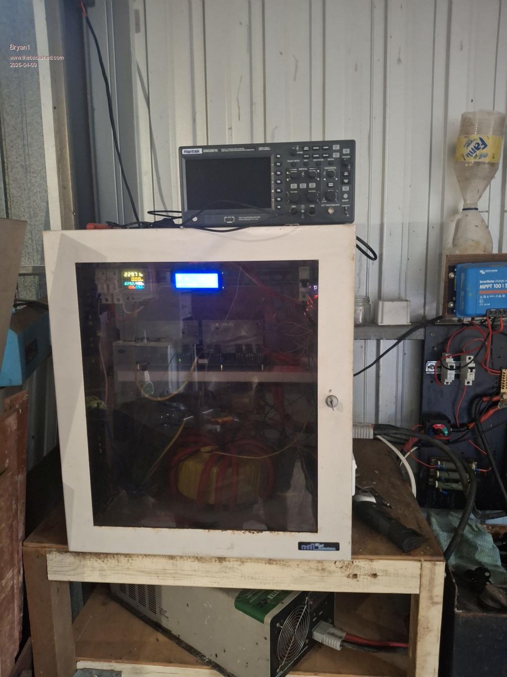
Well Guy's it's pouring down with rain here so what better time to change over the inverters
So I am one Happy Camper this project is finished
Regards Bryan
Bryan1 Guru Joined: 22/02/2006 Location: AustraliaPosts: 2155
Posted: 12:22am 09 Apr 2026
Copy link to clipboard
Print this post
Just went for a look and L02 is where the HS sensor is placed and it's sitting on 40C where the L01 heatsink and the rear ones are cool as so not out of the woods just yet me thinks.
It just hit 45C and the fan came on so I will keep an eye out.
Just put infra red temp change on the L02 mosfets and the second from the end is the problem.
So looks like I'm starting my genset just to power a soldering iron to see if that fix's it. Edited 2026-04-09 10:31 by Bryan1
Bryan1 Guru Joined: 22/02/2006 Location: AustraliaPosts: 2155
Posted: 02:24am 09 Apr 2026
Copy link to clipboard
Print this post
Ok resoldered the offending mosfet and the heatsink is still heating up on L02, I set the starting temp to turn the fan on at 35C and found I did have the fan backwards.
So rather than keep using the genset hooked back up the Kipoint and found as I shared the AC output even with the Anderson connector off line the energy meter is on and the inverter is in the off postion.
So still got to sort out why L02 is heating up, now I have put isolation pads behind both L0 sides so I am wondering if they even need to be isolated.
Page 25 of 28
Print this page
The Back Shed's forum code is written, and hosted, in Australia.