Notice. New forum software under development. It's going to miss a few functions and look a bit ugly for a while, but I'm working on it full time now as the old forum was too unstable. Couple days, all good. If you notice any issues, please contact me.
wiseguy Guru Joined: 21/06/2018 Location: AustraliaPosts: 1326
Posted: 09:04am 08 Oct 2026
Copy link to clipboard
Print this post
Have been thinking about this approach a lot and despite initially thinking it would be an acceptable solution I now think it would not work in the way hoped.
The PWM & Inductor driving the transformer has a very low impedance and drives the transformer for multiples of the 360 degrees continuously. I think it would just drive the constant current source up and down whilst it laughs at the constant current puny "load". The real load that caused the imbalance was at least 1kW (maybe 2).
However if you were to miss a few SPWM cycles (translate to modify the code) and add the DC during that off period then you should be able to step change the flux as desired. I remember some years back when I was chasing the grunt on start-up, during one experiment I attached a 3V cell briefly across the primary I could make the grunt vanish on the next start, changing the polarity of the 3V on the primary made the grunt worse. To clarify, with the inverter off I applied the 3V to the primary briefly then removed it to test the start up, then reversed the polarity and tried again.
This indicates to me that a simple winding and a DC constant current won't cut it as it will just be swamped by the normal inverter drive. So if a mains 4A half wave load causes the DC imbalance in the transformer, to counteract it you will need the equivalent of a mains load of ~4A on the undriven side to balance the flux offset issue or given the 1:8 turns ratio, if you apply it to a winding with the same primary turns a ~32A flux affector (effector?) half cycle would be needed (assuming normal 360° PWM drive).
I now think Poidas approach of modifying the SPWM slightly as required to negate the flux asymmetry (effectively reduce the unloaded 180° amplitude or driving the loaded 180° harder) has the best chance of an elegant solution to this. Edited 2026-10-08 19:07 by wiseguyIf at first you dont succeed, I suggest you avoid sky diving.... Cheers Mike
phil99 Guru Joined: 11/02/2018 Location: AustraliaPosts: 3412
Posted: 11:05am 08 Oct 2026
Copy link to clipboard
Print this post
Yes, that is what I was suggesting the final result would be. The extra winding and DC constant current are just for establishing safe limits for the PWM code modification.
No, not the whole 4 amps. If you look at my diagram the primary and secondary currents are the same but in opposite directions so most of the flux produced by the secondary current is cancelled by the flux produced by the primary current. It is only the small current difference produced by the slight voltage difference on the two half cycles that needs to be cancelled.
A few tens of watts from the DC current source should be enough.
It is similar to the self-saturating mag-amp I mentioned. A DC control power of just 2% of the maximum AC load power pulls the mag-amp cores completely out of saturation, giving maximum inductance and reducing the AC load current to a trickle.
Edit. Silicon Chip did an article on mag-amps Jan. 2023, p68. "Magnetic Amplification & Voltage Regulation by Fred Lever"
In that there is a low voltage example using two Jaycar MT2112 230:12V transformers to make the mag-amp. Edited 2026-10-08 21:57 by phil99
Footnote added 2026-10-09 08:19 by phil99 If you want to skip the experimental extra winding and current source stage, @nickskethisniks (post below this) has shown a +-1% PWM asymmetry to be safe.
Set that as a limit to DC feedback in the PWM code and begin experimenting from there. Use a DC current sensor measuring the difference between primary and secondary, as suggested by InPhase. Average the sensor readings over one or more full cycles to filter out the AC component, leaving just the DC offset that needs to be corrected. The AC component is the normal magnetizing current.
If the hairdryer or heat-gun still have a DC offset increase the 1% limit a little.
nickskethisniks Guru Joined: 17/10/2017 Location: BelgiumPosts: 499
Posted: 02:31pm 08 Oct 2026
Copy link to clipboard
Print this post
As far as the humming/buzz goes, during no load I can pretty sure say it is caused by an assymetric drive (arm psoc controller or hardware, but at the moment I suspect the powerboard more). I swaped the transformer connections and I did not needed to change the polarity of the compensation, so its not the transformer or inductors.
Just introducing a small constant % imbalance between pos and neg modulation cleared the buzz, so maybe this is something to potential add to the firmware, a fixed imbalance between -1.00 and +1.00%. Maybe this could solve no load hum.
I need to investigate the hardware imbalance a bit further to actually see what's causing it, maybe some tollerance issue between my fod3182 drivers.
EDIT:
Also I use a transformer running at 1.45T at nominal voltage, so a small imbalance will let the transformer saturate /hum sooner.
I tried to integrate the voltage of an auxillary winding and current. I made a small "auto" balance function based on the integrated voltage. And while it removed the hum, at a certain moment it went the wrong way and it got stuck in the wrong direction and could not get out. So I need to work on it a bit more. (I let AI help me a bit with finding a good algorithm) Edited 2026-10-09 02:29 by nickskethisniks
wiseguy Guru Joined: 21/06/2018 Location: AustraliaPosts: 1326
Posted: 04:56am 09 Oct 2026
Copy link to clipboard
Print this post
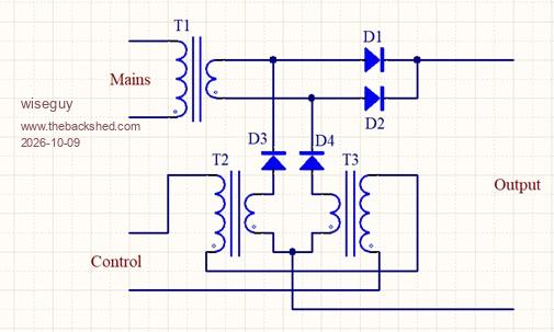
In my view, the operation of the "magnetic amplifier" in the silicon chip article is a bit of a misnomer as I think it is more of a current amplifier using an external current to control saturation which is the actual control mechanism. In layman terms, with no control current the control transformers quickly achieve a level of saturation thanks to the DC steering diodes and passes high current to the load.
The trick is to feed some current during the 180 degrees of no current flow ie causing a net change in the control transformers inner flux that will alter the current passing to the load on the next half cycle - ie we can reduce or increase the final load current.
It appears to me that by varying the control flux level we can now control the point that saturation occur, ergo controlling output energy. So I guess it is a pseudo magnetic control but I don't concur with the simple term "magnetic amplifier".
I also don't concur that the circuit is in its simplest form as the two LHS diodes of the diode bridge could be opened and have the control flux transformer primaries in series with them (yes change the phase of one...) and save 2 diodes. Then the AC inputs to the bridge connect directly to the 20VAC from the main transformer with less diode losses overall.
To restate, it appears that the small milliamp control signal does its magic during the 180 degree off portion of the control transformer - it needs that off time to alter the existing flux with the small control current without having to fight the output current flow flux which it would otherwise need to overcome.
This is why I believe that a control current to fix our sine asymmetry would need to happen when it is not trying to overcome the low impedance drive from the H bridge ie during an off period.
I decided to check magnetic amplifiers in Wiki before I post the above as I wanted a second opinion, their definition is;
"A relatively small DC current on the control winding is able to control or switch large AC currents on the AC windings. This results in current amplification."
Simplified topology
From here I will concentrate on the code fix solution going forward. However I am also wondering if a solution which could add extra dead time (with external circuitry not affecting the code) to in effect reduce the drive only to the unloaded 180 degrees. I did some quick maths and a change of ~1% should be able to be achieved by adding up to a few hundred nano seconds of dead time to each of the HFPWM drive pulses...If at first you dont succeed, I suggest you avoid sky diving.... Cheers Mike
phil99 Guru Joined: 11/02/2018 Location: AustraliaPosts: 3412
Posted: 05:32am 09 Oct 2026
Copy link to clipboard
Print this post
I suppose the term "Magnetic Amplifier" was intended to be used the same way as "Valve Amplifier" or "Transistor Amplifier" denote the mechanism of amplification, rather than the input being amplified.
analog8484 Senior Member Joined: 11/11/2021 Location: United StatesPosts: 242
Posted: 03:44pm 09 Oct 2026
Copy link to clipboard
Print this post
The enhancements being discussed for half-wave loads should/may help since the interactions between GTI backfeed and loads like EV charger and wood splitters often mimic unbalanced loads but more dynamic than repetitive half-wave loads. So, addressing half-wave loads would be a good first step.
analog8484 Senior Member Joined: 11/11/2021 Location: United StatesPosts: 242
Posted: 04:00pm 09 Oct 2026
Copy link to clipboard
Print this post
Maybe or it could be several components in the power chain.
What did you use for the integration period? Was it sync'd to the mains cycles/zero crossings? I suspect accurate imbalance detection/measurement would likely be much more challenging than the actual correction.
nickskethisniks Guru Joined: 17/10/2017 Location: BelgiumPosts: 499
Posted: 09:07pm 09 Oct 2026
Copy link to clipboard
Print this post
Yeah, It could all add up and be anything causing the imbalance.
At the moment I'm sampling at 20khz, synchronized with the carier frequency. I'm using centre alligned pwm so the sample is taken in the middle of the pwm block. Maybe there is a better moment but it looks a good moment, measurements look stable.
Yeah, measurements at no load could be different from measuring during load. I did not test above +200W and it looks usable.
At the moment my board is more a general pwm/pulse generator. I'm gonna make new firmware focussing only on the inverter swpwm and add an output voltage regulation loop to see if than can be implemented safely.
phil99 Guru Joined: 11/02/2018 Location: AustraliaPosts: 3412
Posted: 07:07am 11 Oct 2026
Copy link to clipboard
Print this post
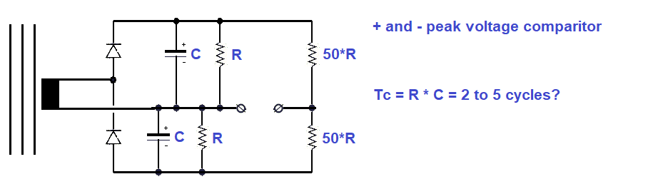
Although the average voltage of your sensing secondary will always be 0V there might be some distortion of the positive or negative peak that is closest to the saturated side of the primary current. If this is the case comparing the positive and negative peak voltages may give a consistent indication of which way to adjust the PWM offset.
To test this idea vary the PWM offset** between +1% through 0% to -1% while monitoring the output of this circuit. Some experimenting with component values will be needed. This voltage may be quite small so amplification could be needed. Depending on the voltage of your sensing winding this circuit's + & - rails might be able to power an op-amp. Edit. Thinking about it a bit more, perhaps the time-constant should be 10 or more cycles (200mS).
If the caps. are 22µF then R = 10kΩ for 220mS Use 1% resistors for the voltage divider.
** Or you could put a diode in series with your 200W load. Test with diode in both directions, and without it. . Edited 2026-10-11 20:33 by phil99
InPhase Senior Member Joined: 15/12/2020 Location: United StatesPosts: 189
Posted: 04:48pm 11 Oct 2026
Copy link to clipboard
Print this post
We have a couple of different ideas on how to mitigate this imbalance. Are we trying to add volt-seconds to the other side to balance it back out by altering the PWM symmetry, or are we physically adding flux in the appropriate direction with another winding? Two very different solutions that both require a method to sense the imbalance.
analog8484 Senior Member Joined: 11/11/2021 Location: United StatesPosts: 242
Posted: 05:55pm 11 Oct 2026
Copy link to clipboard
Print this post
That's likely. For the no load hum/imbalance, the imbalance detection/measurement is likely always indicated by small differences in the integral of the aux winding voltage. Reliable and accurate detection/measurement of small differences are always more challenging especially in the presence of a much larger baseline signal. What is the current detection algorithm you are using?
poida Guru Joined: 02/02/2017 Location: AustraliaPosts: 1497
Posted: 06:30am 12 Oct 2026
Copy link to clipboard
Print this post
time to have a play.
I have modified my inverter test bed. I now have a 1600V 70A diode in series with the 240V AC output which I have added a switch to short this diode. this way I run it "normal" or "perverted" just by flicking a switch.
I run this supply against my 100 - 400W resistive AC load.
there is a current sensor, 0.0208 V/A on the primary winding.
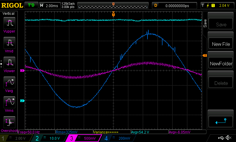
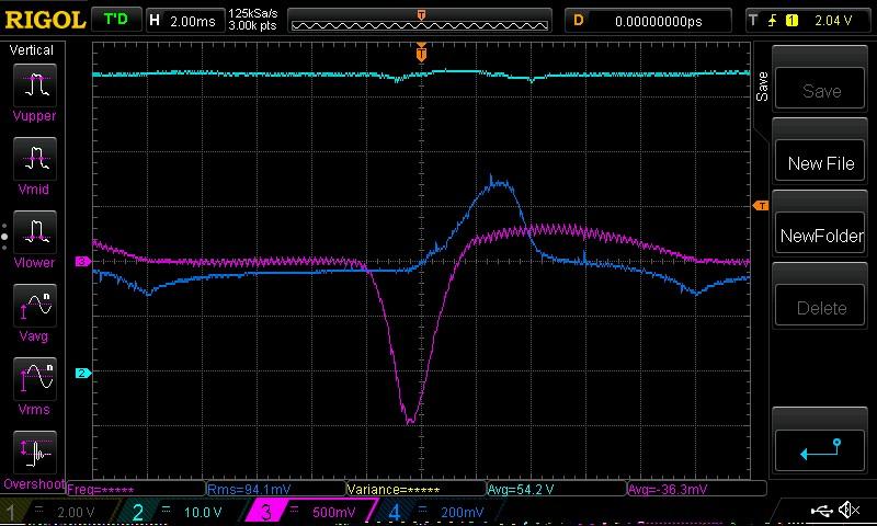
Light Blue is DC volts, measured at the +DC bus location on the inverter board. Dark Blue is AC volts, as supplied to the load. Purple is smoothed DC current in the primary winding.
at 200W, with diode shorted is this:
and with the diode in circuit it is this:
notice the Purple average value, lower right in both images. With the diode in circuit there is rather a lot of noise from the toroid, as to expected.
My plan is to modify SPWM amplitude to make it not symmetric and use as input the primary current. I will go for a value above some small offset, say about 7mV from the 0.0208 V/A current sensor.
Depending on the sign of the offset, I will modify one or the other 1/2 cycles, bring it's amplitude down a bit, until the current gets below some threshold.
but it's time for beer now so code changes will have to wait for an other day.
p.s. thanks Mike for the box of goodies you gave me. I used one of the VS70HF160 diodes you gave me. perfect for this.wronger than a phone book full of wrong phone numbers
wiseguy Guru Joined: 21/06/2018 Location: AustraliaPosts: 1326
Posted: 07:45am 12 Oct 2026
Copy link to clipboard
Print this post
If you ever manage to kill it, plenty more where it came from.
A question; The dark blue mains voltage seemed to collapse with the diode in circuit (second pic) something doesn't look right?
Been thinking more about what detection/cure can be used. If a centre tapped sense winding was put on the toroid could we use a summing integrator or dual integrator to each end of the sense winding, if the waveform was symmetrical then the integrators output is zero? Else it is proportional to the difference, telling us which 180° to control?
or
What current sensor are you using - is it the TLS76? If a second sensor is placed on the primary winding, with a resistive divider the same ratio as the primary/sec turns in theory they should be able to be ~neutralised. Then if saturation starts there will be a steep rise in primary with no corresponding rise in secondary. If the rise passes a threshold the rest of the PWM pulses for the remainder of the 180 degrees could be truncated by the nano - any further pulses are just going to make a bad situation rapidly worse, we need to pull it out of saturation not drive it in further.
Not sure if any of these thoughts are useful but maybe it could be a second level "fix" if the +/- 1% tweak fails to keep the Sine drive under control ?
Enjoy the beers.If at first you dont succeed, I suggest you avoid sky diving.... Cheers Mike
nickskethisniks Guru Joined: 17/10/2017 Location: BelgiumPosts: 499
Posted: 10:51am 12 Oct 2026
Copy link to clipboard
Print this post
I do something like this:
I just calculate the error = setpoint - measured balance. If: error = negative then pos + 0.1 and neg -0.1 error = positive then pos -0.1 and neg +0.1
I can adjust the deadband so it's not reacting to fast.
But maybe the direction is wrong and that's why it drifts to the wrong way.
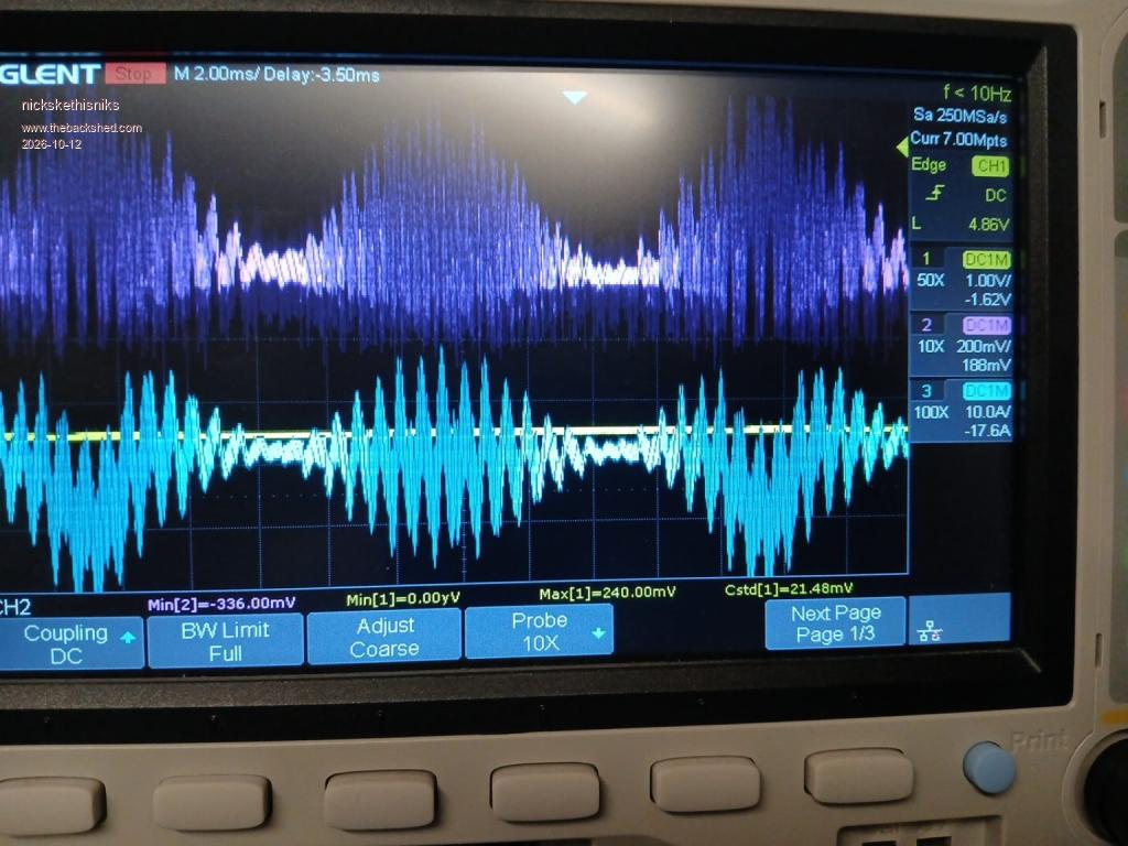
I do find that ultimatetly measuring current is the way to go, here you can see a no load situation with a current measurement: (but the transformer with a noticeable buz). When there is no buz the current is 100% symetric.
The blue is the primary current (between inductor and transformer) wave measured with a micsig CP2100B probe the other is random CT (2500T 70A rated) with a 100R burnden resistor after a full bridge rectifier (no rc, only adc as load).
You can clearly see a shifted current during a half period, so something is possible based on just the peak current alone. This is a no load situation so this could be even easier to spot with high currents.
(next time I will try to capture the scoop images over the ethernet instead of taken a gsm picture of it. )
Edited 2026-10-12 20:55 by nickskethisniks
johansen Newbie Joined: 01/08/2014 Location: United StatesPosts: 13
Posted: 06:02pm 12 Oct 2026
Copy link to clipboard
Print this post
Seems to me the only way to measure this problem without advanced filtering of the primary current, is to put a magnetic sensor in the core to detect the offset.
A highly sensitive core such as a metglas tape wound core: if it is used as an auxiliary transformer to measure the voltage offset from the inverter, it will only detect the offset voltage being supplied to the transformer by the impedance (and pwm table) of the inverter.
Since the inverter impedance is probably higher than the toroid primary copper, you could run with just that signal and see how far you get.
here's an idea:
If you measure the current into that aux coil, (using a closed loop hall effect sensor) and set a trigger so if the current exceeds X, it begins to pulse an interlock on the corresponding Gate driver of your inverter to deliver less voltage on the corresponding half cycle.
I do agree that you can subtract the secondary current from the primary current by sending both through a single current, closed loop current transformer. It seems to me you should get a useable magnetizing current signal out of it and use that to correct the pwm generation somehow. Edited 2026-10-13 04:04 by johansen
poida Guru Joined: 02/02/2017 Location: AustraliaPosts: 1497
Posted: 02:10am 13 Oct 2026
Copy link to clipboard
Print this post
I sampled the AC voltage at the exact point where the load is applied, that is, after the 1uF filter cap, tiny Vfb transformer etc.
It's fun switching the diode in and out of circuit while the inverter is powering the load.
when in circuit, the lights dimmed a fair bit and we can see why in the AC waveform. There are much lower voltages and in the case of one 1/2 wave, not a lot at all. The lights are pure resistive incandescent lights so power is proportional to voltage.
I feel very confident the AC voltage trace is what is output.wronger than a phone book full of wrong phone numbers
poida Guru Joined: 02/02/2017 Location: AustraliaPosts: 1497
Posted: 02:41am 13 Oct 2026
Copy link to clipboard
Print this post
I am using a LEM current sensor, where zero current is approx 2.50 V I added a thick shunt, to permit measurements up to about 110 Amps without saturating the sensor's output. I use the 4 wire version, that includes the 2.5V offset voltage on one pin and the output relative to this on another pin.
The average voltage of the current sensor channel is good enough for me to have a crack at the SPM modulation control idea. But there is nothing stopping using the current sensor sampled at about 4kHz to detect these large peaks. The nano code's main loop() is running at about 4kHz and there is a large amount of spare time to do the peak detection and sampling of the sensor output.
The sensor is 0.0208 V/Amp so this peak current is 1.5V or 72 Amps DC The average value is over the displayed time range, or 1.2 complete AC cycles and is about 1.75 Amps DC.
I think I will use the DC current sensor approach since it is simple to install and remove, it's easy for me to understand and interface to the nano's ADC input and the programming will be fun to explore. Also I will probably put a RC low pass filter on the current sensor output, to reduce the PWM components to about 1/10th of the signal of interest.
No doubt we can work out better approaches which will have very compelling reasons to build them. As usual I like your integrating of a differential output idea.
One of the next things I want to look at is how fast the toroid progresses into the state where it's saturated for a portion of a cycle, once I flick the diode switch. This will give us some feel for how fast the control system needs to respond. Questions such as how many cycles of how much saturation is tolerable need to be thought about too.wronger than a phone book full of wrong phone numbers
analog8484 Senior Member Joined: 11/11/2021 Location: United StatesPosts: 242
Posted: 05:17pm 13 Oct 2026
Copy link to clipboard
Print this post
I suggest trying the following for testing to help determine if there is a direction problem: error = negative then pos no change and neg -0.1 error = positive then pos -0.1 and neg no change
Thanks for getting the scope captures. Current sensing solutions should be more robust. The CT primary current waveform makes the imbalance very clear. Comparing the peaks is probably fine for no load but might be too simplistic for real loads.
wiseguy Guru Joined: 21/06/2018 Location: AustraliaPosts: 1326
Posted: 11:58pm 13 Oct 2026
Copy link to clipboard
Print this post
Will be very useful to develop an effective solution.
I see it that comparing the peaks of individual half cycles, regardless of load, as a valuable tool to make immediate adjustments to the next half cycle or the next two half cycles. Reducing the amplitude of the unloaded portion would definitely help but there are two other things to consider.
1) It is not the over drive on the unloaded portion that started the issue it is the reduced drive due to the large half wave load that we just applied. The first and earliest cure would be to increase the next half wave "driven half-wave portion" lets say an arbitrary figure of 0.1% gain and consider to reduce the next unloaded half by the same figure.
The concept is that we might be able to stop the toroid entering saturation territory, instead of trying to later cure a serious saturation event. When Poida looks at the time and no of cycles to enter saturation we will have a better idea of whether we can do something in time. If he also looks at the reduction of the loaded peak the "tweaking" values should make it easier to predict the % drive changes required?
2) In an effort to reduce mains fluctuations it feels it would be better to consider trying to restore the driven (half-wave) loaded 180° as much as possible. It is due to the inverters total impedance that the reduced magnetisation occurred during the driven time and we no longer have our full mains (240V?) either, despite the unloaded 180° still providing ~ the same amplitude as before. By the time we have been able to evaluate the previous two 180° peaks, we have under magnetised half the waveform and effectively over magnetised the unloaded portion. That is why I feel we probably need to be making corrective adjustments to both halves ASAP to get back to a better equilibrium and be closer to the original mains output p-p than just reducing the unloaded 180°.
There is no question re the primary current increase as we are entering saturation territory and could also be a very useful magnifier to what-ever adjustments we are making to try to keep the magnetising currents balanced.
If we can ever solve this can of worms effectively, it will be a great result. Edited 2026-10-14 10:18 by wiseguyIf at first you dont succeed, I suggest you avoid sky diving.... Cheers Mike
poida Guru Joined: 02/02/2017 Location: AustraliaPosts: 1497
Posted: 03:16am 15 Oct 2026
Copy link to clipboard
Print this post
I had a bit of time to look at the code I will try:
(I now need two sets of PID loop variables, so that means time to use arrays)
i_balance is a float, that will be able to move from -0.9 to +0.9 and preferably remain close to 0.0, which will mean a near zero DC primary current I_balance is the running correction factor that the pid loop works with.
This will obtain the DC current, remove the 2.5V zero offset and return a value in Amps for my sensor. This line will execute about 4kHz and so give a decent average of the current.
now the big change:
This is the main control code that executes at 100 Hz, near the AC output zero crossing point.
if (sst == 251) // once sst = 251, run PID. the above bang-bang control will NOT have executed, because sst = 251 { Setpoint[0] = ac_setpoint; Input[0] = ac_output; do_pid(0); pwr = pwr + Output[0]; // // alter the balance of the AC waveform, reduce V1 or V2 in accordance with the primary current imbalance control factor // // Setpoint[1] = 0.0; // zero current required Input[1] = primary_current; do_pid(1); i_balance = i_balance + Output[1]; if (i_balance > 0.9) i_balance = 0.9; if (i_balance < -0.9) i_balance = -0.9; // // assumes v1_active = 0 during negative part of AC cycle. This must correspond with primary current sensor sense // // if current is -ve, means 1/2 cycle when v1_active = 0, so alter vpwr_v2 and make it smaller // else // if current is +ve alter vpwr_v1 and make it smaller // }
How it works is first run pid control on the AC output voltage, using Vfb as the input. I end up with the float "pwr" which is basically a volume knob for the AC voltage. Next I run the pid control on the DC current input, this will alter i_balance in some way, making it more negative or more positive as needed to bring primary_current back to something small.
The new bit is there are now two 32 bit vpwr variables, one for each half cycle. Depending on the sign of i_balance, I need to alter one of these vpwr values or the other.
finally a bit of a change is needed in the Timer1 interrupt
if (v1_active == 1) // alternate between 2 output compare pins. Get a full 50Hz waveform { c = (l[pcount] * vpwr_v1) >> 16; // scale sine wave by vpwr, 32 bit integer calcs. 16 bit shift fastest of all OCR1B = c; // was c 1/2 out this pin } else { c = (l[pcount] * vpwr_v2) >> 16; OCR1A = c; // and then 1/2 out this pin. }
this takes the two vpwr values and obtains the required PWM width for either 1/2 cycle which is active at that time.
My thinking is based on looking at the inverter driving a resistive load which would have primary AC current being proportional to primary AC voltage, and importantly having the same sign. The code will see maybe a large negative DC average current and so will reduce the 1/2 wave that does the negative voltage and leave the positive half wave unchanged. If a positive DC average current appears, then the positive 1/2 wave will be reduced. I'll bet that it is never going to be as simple as this. Edited 2026-10-15 13:25 by poidawronger than a phone book full of wrong phone numbers
Page 2 of 3
Print this page
The Back Shed's forum code is written, and hosted, in Australia.

 Notice. New forum software under development. It's going to miss a few functions and look a bit ugly for a while, but I'm working on it full time now as the old forum was too unstable. Couple days, all good. If you notice any issues, please contact me.





 Print this post




 )