Notice. New forum software under development. It's going to miss a few functions and look a bit ugly for a while, but I'm working on it full time now as the old forum was too unstable. Couple days, all good. If you notice any issues, please contact me.
InPhase Senior Member Joined: 15/12/2020 Location: United StatesPosts: 189
Posted: 01:13pm 19 Jul 2026
Copy link to clipboard
Print this post
Hello all! I have been looking over the code used for the nano and pico inverters in an effort to truly understand what is going on "under the hood/bonnet". I notice that the sine table currently uses
3.14159 /(NPWM - 1)
That puts both zero-degree and 180-degree zero crossings into the same 200-sample half-cycle. The next half-cycle also begins at zero, giving two consecutive zero samples and slightly nonuniform phase spacing. On the scope, that looks like a very tiny flattening at the zero crossing. I haven't noticed any adverse electrical effects, but it would raise the THD. Has anyone else seen any ill effects?
If the math were altered slight so that the half cycle doesn't come around to zero at the end, that would eliminate the double zero at the crossing.
poida Guru Joined: 02/02/2017 Location: AustraliaPosts: 1497
Posted: 12:51am 20 Jul 2026
Copy link to clipboard
Print this post
what I wrote works well enough.
But why not give it a go and see if things improve.
I spent a good amount of time working with the area where the PWM changes from D9 to D10 and also the D10 change to D9.
I found the order of actions that set up the PWM is important and the code with "perfect_symmetry" in the name is ideal.
Possibly removing the extra zero in the sine table will be good. I expect there will be some other "out by one" mistakes in there and maybe one of those deals with the extra zero just by accident.wronger than a phone book full of wrong phone numbers
KeepIS Guru Joined: 13/10/2014 Location: AustraliaPosts: 2282
Posted: 01:28am 20 Jul 2026
Copy link to clipboard
Print this post
FYI:
HIOKI Power Quality Analyzer.
Power to the property with all normal loads running:
Total Harmonic Distortion:
AC from Mains: 2.5% AC from Inverter: 2.3%
Virtually the same first 5 odd harmonics and all below 2.3%.
The Inverter THD when isolated from Property, just Inverter THD, unloaded and loaded with a resistive load..
No Load: 0.9% THD
2.3kW: 0.6% THD.
Almost all fundamental frequency, which is exactly what you want, the first and second odd harmonics are tiny, the third barely visible, nothing after the 3rd odd harmonic, and this tester reads out to the 37th harmonic.
From memory, anything under 3% in a typical inverter is considered good enough.
KeepIS Guru Joined: 13/10/2014 Location: AustraliaPosts: 2282
Posted: 01:42am 25 Jul 2026
Copy link to clipboard
Print this post
In the code Poida posted, indexes [0 to 199] of the array are used [200] 199 does not appear to be zero on the very quick look that I had, it's been a long time though. . Edited 2026-07-25 14:12 by KeepISNANO:Inverter V 8.4ks - Linux AvrDude GUI script V4.1
KeepIS Guru Joined: 13/10/2014 Location: AustraliaPosts: 2282
Posted: 01:25am 26 Jul 2026
Copy link to clipboard
Print this post
Well I decide to make time, go back and have a better look at the 1/2 sinewave table, and indeed InPhase is correct, Table Index[199] is indeed around 0, before wrapping around to Index[0] which is also and correctly 0.
BTW: The code currently generated is 100% proven and 100% rock solid under any load condition, as I would expect, and as indicated, produces very low % THD.
However it has peaked my interest, so I have made a quick change to the code and am in the process of doing some testing for any detectable difference in my bench Test_Inverter. I want to see if I can detect any subtle differences to the performance of the inverter with this slight code change, and if it's even worth changing at all.NANO:Inverter V 8.4ks - Linux AvrDude GUI script V4.1
KeepIS Guru Joined: 13/10/2014 Location: AustraliaPosts: 2282
Posted: 04:52am 26 Jul 2026
Copy link to clipboard
Print this post
Having confirmed that the Sine table is generated correctly and wraps through ZERO once per cycle, there is virtually no difference with one exception, the slightest difference in the sinewave slope in what some refer to as the wobbles, has disappeared entirely, and I mean the slightest change on my test inverter.
There is no change to idle noise or idle current etc. An interesting exercise, I will confirm everything again and carry out heavy load testing before I make a permanent change.NANO:Inverter V 8.4ks - Linux AvrDude GUI script V4.1
KeepIS Guru Joined: 13/10/2014 Location: AustraliaPosts: 2282
Posted: 11:35pm 26 Jul 2026
Copy link to clipboard
Print this post
Confirmed that the slight wobble in the sine wave slope caused by the extended zero crossing duration has been completely eliminated, just a simple 3 character code change.
I resized the ½ sine array to maintain 20kHz and skipped the final zero entry, this keeps AC frequency timing exactly where it was when the final zero was previously included in 20kHz SPWM generation.
User InPhase is correct in that any wobble or misshape in the sine wave is a distortion product that would increase THD, however, THD is very low in this inverter and as the disturbance was extremely small, I doubt that I will see any real difference in THD when I retest the code in the Off Grid Inverter under load.
When I've torture tested it, I'll post an updated file for anyone interested.
EDIT:
My Test Toroid is an old Aerosharp with existing compromised secondary winding and 27 turn primary chucked on, easy to make it hum.
THD tested with no Load - most Inverters usually produce higher THD under no load.
Running the existing, slightly extended zero crossing code, THD is 0.8% to 0.9%, with only 9 small harmonics.
Running the modified Sine array and code, THD is now 0.4% to 0.5%, with 1 tiny close harmonic, which in big reduction in what was, an extremely low THD at Idle.
However 0.4% difference will hardly register under a typical household load of 1.6% to 2.4%, BUT! there is a difference, and it was worth the small amount of time to make the WG Inverter specs even better.
KeepIS Guru Joined: 13/10/2014 Location: AustraliaPosts: 2282
Posted: 02:04am 28 Jul 2026
Copy link to clipboard
Print this post
Code is running in the Dual off grid Inverter, everything perfect, typical THD caused by lots of plug packs, Inverter-fridge, air-con PC's screens all SMPT plug packs etc, is around 2.6%, add a 3kW Restive load to the mix (Hot Water system) and THD drops to 1.6%, so impossible to detect a small difference as THD is constantly shifting around with changing load conditions from the workshop and Home.
KeepIS Guru Joined: 13/10/2014 Location: AustraliaPosts: 2282
Posted: 07:07am 31 Jul 2026
Copy link to clipboard
Print this post
I wondered why index 99 and 100 were both 65532 in the original code, and why index 100 never gets to 65535. Turns out only one change is actually needed, and the change is to the formula, with the rest of the code unchanged.
NOTE: This is for the Inverter code that poida previously posted near the start of the thread.
With NPWM = 200, changing the sine array algorithm from, (float)(NPWM-1) to (float)NPWM, now generates the correct array dimension with index 0 = 0, 1 = 1029 and 199 = 1029, instead of zero, and removes the compressed double array value at index 99 and 100, the SPWM frequency remains 20kHz.
Nothing else is changed, other code stays as it was originally.
Like the following:
#define NPWM 200 . . for (t = 0, i = 0; i < NPWM; i++, t += 3.14159 / (float)NPWM { u = 65535.0 * sin(t); l[i] = (uint16_t)u; } . . pcount ++; if (pcount >= NPWM) { .... ... .... }
Both methods shown will result in the 1/2 sine array being built correctly for this HW & SW implementation used to generate the intended 50hz/60hz SPWM output waveform.
BTW: The brilliant Inverter code written by poida has run faultlessly for years, this just removes a tiny wrinkle that some have noticed with test gear, I admit that I missed it, as the code output was so good compared to anything else before it.
It had been bought up way back by wiseguy and resurrected again here by InPhase, thanks to both for investigating, testing and pushing us : Edited 2026-08-01 10:18 by KeepISNANO:Inverter V 8.4ks - Linux AvrDude GUI script V4.1
KeepIS Guru Joined: 13/10/2014 Location: AustraliaPosts: 2282
Posted: 01:25am 01 Aug 2026
Copy link to clipboard
Print this post
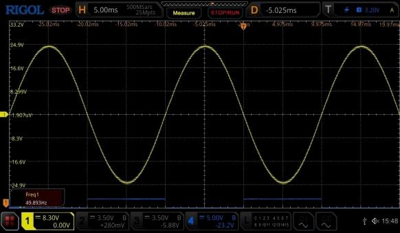
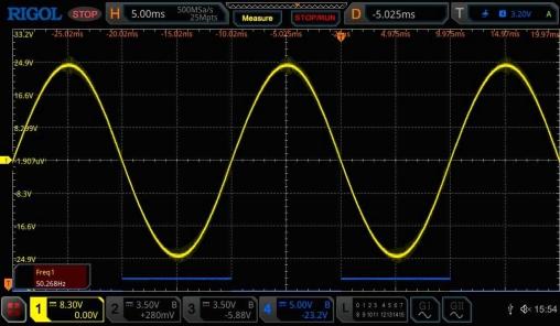
FYI: I had been looking at the AC output on the test inverter without an AC output filter. Now, with the slightest 20khz fluff removed from the peaks, this AC sine wave is as perfect as my precision sine wave oscillator and analogue osc.
I'm not trying to embellish this, it's visually perfect, this is not what I would expect to see from any high power Inverter.
Using a Rigol MSO5354 In DOT mode, which gives higher fine detail resolution, and looking at single and multiple sine waves for timing precision with respect to 0, 90, 180, 360 deg zero crossing and peak envelope symmetry, it looks absolutely perfect, with not a single wobble or imperfection of the slope or zero crossing.
Would be interesting to know what others find if you get around to looking at it, also latest version uploaded.
I just tested a small 2.5kW / 5kW peak, HF pure sine Inverter, 1.7% THD at idle, sine wave has small wobbles on both sides above and below zero crossing, and 15 small harmonics, it would never in a million years be mistaken for a sine-wave generated by a quality piece of workshop test equipment, the WG Inverter output does, and currently indicating 0.4% THD.
DOT mode capture always looses intensity, these are with the inverter completely unloaded, and NO bandwidth limiting (350MHz).
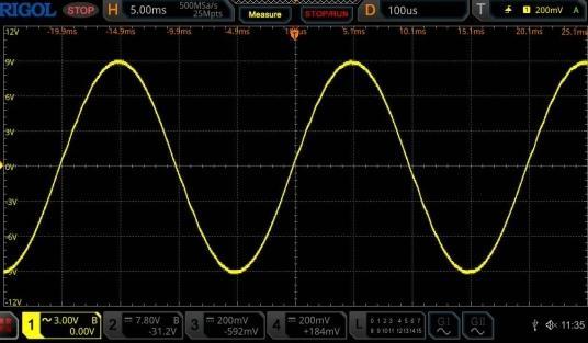
Below: I realised that all my uploaded captures have been with a small resistive load, or under higher testing loads. Below is the unloaded, unmodified code on the test Inverter, most unloaded AC outputs posts from most builds in the past have had wobbles, some have a lot, but look reasonable with a few hundred watts of resistive load applied, even this last unloaded capture still looks good to me, it was basically thought of as good as you can get, but it's not as clean as the first two above with the slightly modified sine array.
We normally put this wobbles down to choke interactions and/or layout, wiring etc.
InPhase Senior Member Joined: 15/12/2020 Location: United StatesPosts: 189
Posted: 02:05pm 14 Aug 2026
Copy link to clipboard
Print this post
The Poida Nanoverter code has been running on my 4 kW plywood mounted inverter for several years now without any issues. My intent was not to poke holes in a virtually flawless work. I am in the process of upgrading the system at the off grid super-secret remote cabin and started going back over everything. It just kinda clicked in my brain that that piece of the c ode would wrap back to zero immediately following a zero. Having said that, I don't see any real need to change it in an already running system. Just a curiosity.
KeepIS Guru Joined: 13/10/2014 Location: AustraliaPosts: 2282
Posted: 11:22pm 14 Aug 2026
Copy link to clipboard
Print this post
That's fine, likewise mine running for years and poida has had his running for way, way longer. My high power inverter has been running with the correct sine table for 2 weeks now and peaking around 14kW, obviously it runs without issue either way. I must say that I'm very envious of your self sustained remote location plans, hope it all works out for you.NANO:Inverter V 8.4ks - Linux AvrDude GUI script V4.1

 Notice. New forum software under development. It's going to miss a few functions and look a bit ugly for a while, but I'm working on it full time now as the old forum was too unstable. Couple days, all good. If you notice any issues, please contact me.


 Print this post